

PLASMA FUSION COHERENCE ENGINEERING DEVICE
can compensate for asymmetric plasma density distribution inside the orb ⦁ Control system for four independent quadrant drivers needs to be defined — OPEN VARIABLE T1 / T2 / T3 — TESLA COIL ARRAY Three Tesla coils arranged around the orb zone. Primary function is rotating magnetic field generation for kink instability suppression and plasmoid coherence enhancement. The rotating field is the EVO/Cooper pair analog — driving coherent electron organization in the plasmoid. PARAMETER VALUE / STATUS Count Three coils Arrangement OPEN VARIABLE — fixed 120 degree or adjustable spacing Frequency control OPEN VARIABLE — independent per coil or phase shifted single source Primary function Rotating magnetic field — kink instability suppression Secondary function EVO coherence enhancement — rotating field drives charge cluster organization Activation Stage 2 — active through Stage 5 Interaction with C3 Complementary kink suppression — two independent systems Field strength OPEN VARIABLE Drive signal OPEN VARIABLE Tesla Array Design Notes ⦁ Three phase at 120 degree spacing produces smoothest rotating field — same principle as three phase AC motor stator ⦁ Rotating field frequency is a primary tuning variable — sweep to find plasmoid resonance ⦁ EVO formation is encouraged by rotating field — Shoulders charge clusters prefer helical electron paths ⦁ Independent frequency control per coil allows field rotation speed adjustment without rewiring ⦁ The combination of Tesla rotating field and C3 quadrant phase control gives full three dimensional plasmoid stability management ⦁ Tesla coil RF output may interact with RF waveguide input — shielding and frequency separation needed VEM DRIVE — VARIABLE ELECTROMAGNETIC DRIVE Located below C3. Function not yet solidified. Visible in design imagery as a complex toroidal/cylindrical assembly with multiple winding layers. Leading candidates for its role are defined below. PARAMETER VALUE / STATUS Position Below C3 — bottom of full assembly Geometry Complex toroidal/cylindrical multi-winding assembly Function OPEN VARIABLE — see candidates below Candidate 1 Primary ionization source — drives plasma upward into C3/orb zone Candidate 2 Resonance driver — drives the plasmoid at its natural frequency Candidate 3 Field tuning system — fine adjustment of axial field profile Candidate 4 MHD power extraction — converts downward plasma flow to current Drive signal OPEN VARIABLE Power level OPEN VARIABLE VEM Drive Design Notes ⦁ The multi-winding toroidal geometry suggests variable field shaping capability — not a simple solenoid ⦁ If primary ionization: drives plasma seed upward into orb zone from below — feeding Stage 1 ⦁ If resonance driver: must be frequency-matched to plasmoid natural frequency — requires Langmuir probe feedback ⦁ If MHD tap: downward plasma leak from C3 is converted to current — does not disrupt upper confinement ⦁ Function determination is a priority before build proceeds — it affects C3 geometry and spacing decisions AUXILIARY SYSTEMS UV Input — 254nm Ultraviolet ⦁ Bilateral input at C2 level — both sides of confinement zone ⦁ 254nm is the optimal wavelength for air/nitrogen photoionization ⦁ Lowers plasma breakdown threshold — reduces required HV for ionization ⦁ Continuous UV during Stage 1 and 2 — may reduce or switch off during Stage 5 ⦁ UV at C3 base level — OPEN VARIABLE ⦁ UV exposure to operator — full UV shielding mandatory during operation ⦁ Ozone production from 254nm UV in air — ventilation required RF Waveguides ⦁ Bilateral input at C2 level — matched to UV lamp positions ⦁ RF heats plasma in the confinement gap zone ⦁ Frequency tuning to ion cyclotron resonance maximizes heating efficiency ⦁ Ion cyclotron frequency for air plasma at target field strength — OPEN VARIABLE pending field strength spec ⦁ RF and Tesla coil frequencies must be separated to avoid destructive interference ⦁ Waveguide geometry determines beam width and penetration depth into orb zone ⦁ [OPEN VARIABLE] RF frequency range and power level ⦁ [OPEN VARIABLE] Waveguide geometry and coupling method POWER EXTRACTION — THERMAL TO ELECTRICAL Heat is a primary output of the stable plasmoid. Rather than treating thermal output as a management problem, this design treats it as a co-equal output stream alongside any direct electrical extraction. Three conversion layers are proposed in cascade. Layer 1 — Direct Electrical (Primary) ⦁ MHD tap or thermionic extraction from the C2 gap zone — 2.5" between C2 inner surface and orb boundary ⦁ Highest quality energy — direct plasma-to-electrical conversion ⦁ Electrode material — graphite or thoriated tungsten preferred for plasma compatibility ⦁ Output: raw DC requiring rectification and filtering ⦁ [OPEN VARIABLE] Extraction method — MHD tap vs thermionic vs combined ⦁ [OPEN VARIABLE] Electrode geometry within C2 gap Layer 2 — Thermoelectric (Secondary) ⦁ TEG modules mounted on coil housings and chamber walls ⦁ Seebeck effect converts temperature differential to DC ⦁ Passive — no moving parts, no control system required ⦁ Captures heat that escapes the primary extraction zone ⦁ Stacks onto Layer 1 output — additive not competitive Layer 3 — Stirling or Thermionic (Tertiary) ⦁ Captures remaining low-grade heat after Layer 1 and 2 ⦁ Stirling engine — simple, reliable, no exotic materials ⦁ Thermionic converter — cesium vapor type, high temperature operation ⦁ Third output stream — diminishing returns but zero added plasma complexity Power Budget Reality Check ⦁ Input power: coil drives + Tesla array + UV lamps + RF waveguides + VEM drive ⦁ First target: breakeven — Layer 1 output equals total input ⦁ Second target: net positive at Layer 1 alone ⦁ Third target: Layers 1+2+3 combined exceeds input by meaningful margin ⦁ Do not assume net positive before bench measurement — instrument first ⦁ [OPEN VARIABLE] Total input power budget — must be defined before efficiency targets are meaningful MODULAR ADJUSTABLE FRAME SYSTEM v2.7 ⦁ Precision modular rail construction — four vertical rails, adjustable horizontal cross members ⦁ Structural mounting decks at C1, C2, C3 levels — precision coil positioning platforms ⦁ Precision positional adjusters on all coil positions — coil spacing is a primary tuning variable ⦁ Coil spacing adjustment changes mirror ratio — primary tuning for plasmoid size and stability ⦁ Frame allows C1 and C3 to slide axially — adjustable orb zone height ⦁ C2 saddle coil position adjustable — equatorial centering ⦁ Heat clearance space at top — noted in v2.7 documentation ⦁ Rapid iteration modular design — optimized for development phase flexibility ⦁ Designed for upgrade to full precision machined enclosure in production versions INSTRUMENTATION REQUIREMENTS Blind tuning of a plasmoid confinement system is inefficient and potentially destructive. The following instruments are required to tune the device intelligently. Essential — Required Before First Power On ⦁ Oscilloscope 100MHz+ — drive signal verification, RF frequency, pulse timing ⦁ HV probe 10kV+ — voltage measurement at ionization electrodes ⦁ Gaussmeter — field strength at C1, C2, C3 positions ⦁ UV meter — confirm 254nm output and intensity at orb zone ⦁ Current probe — drive current monitoring all coil channels Required for Tuning Phase ⦁ Langmuir probe — plasma temperature and density inside orb zone ⦁ RF power meter — input vs reflected power at waveguide ⦁ Thermocouple array — thermal mapping of coil housings and chamber ⦁ Spectrometer — plasma emission spectrum confirms species and temperature ⦁ High speed camera with UV filter — observe plasmoid structure and stability Power Measurement ⦁ Precision watt meter on input — total power consumption ⦁ DC volt/current meter on Layer 1 output — primary extraction measurement ⦁ TEG output measurement — Layer 2 contribution ⦁ All measurements simultaneous — efficiency calculation requires concurrent data SAFETY This device operates at high voltage, generates UV radiation, produces strong and rotating magnetic fields, and sustains a high temperature plasma. All precautions are mandatory. ⦁ High voltage interlock — physical interlock on all HV circuits before access ⦁ UV shielding — full enclosure or UV-blocking face shield, NO exceptions ⦁ Ozone ventilation — 254nm UV in air produces ozone, dedicated exhaust required ⦁ Rotating magnetic field — pacemaker wearers must not approach ⦁ Ferrous tools secured — rotating field will attract and accelerate steel objects ⦁ RF exposure — maintain safe distance during waveguide operation ⦁ Thermal — plasmoid and coil temperatures can be extreme, no contact during operation ⦁ Capacitor discharge — bleed resistors mandatory on all HV capacitor banks ⦁ Single point ground — all chassis grounds to single earth ground ⦁ Fire suppression — CO2 extinguisher within reach during all test runs ⦁ Never operate alone — two person minimum during powered testing DEVELOPMENT SEQUENCE Build order follows risk and dependency. Resolve open variables before committing to hardware. 1. Resolve VEM drive function — this affects C3 geometry and spacing decisions 2. Define power input budget — sets scale of all downstream components 3. Specify coil windings — wire gauge, turns, core for C1/C2/C3 4. Build and test C2 saddle coil alone — verify field geometry with gaussmeter 5. Add C1 and C3 — verify mirror geometry and orb zone field profile 6. First plasma attempt — UV only, low voltage, verify ionization 7. Add RF waveguides — verify heating effect with Langmuir probe 8. Add Tesla coil array — verify rotating field with gaussmeter sweep 9. Attempt Stage 5 stable plasmoid — tune spacing, RF frequency, Tesla rotation 10. Install power extraction — measure Layer 1 output against total input 11. Add TEG Layer 2 — measure additive contribution 12. Document all anomalous signatures throughout — EVO research runs in parallel PLASMA FUSION COHERENCE ENGINEERING DEVICE — Planning Document v2.0 Confidential — Proprietary Research
Updates
Prayer Requests
Click the Pray button to let the fundraiser owner know you are praying for them.
PLASMA FUSION COHERENCE ENGINEERING DEVICE
Fundraiser created byRoger Brock
Fundraiser funds will be received by Roger Brock
Recent Donations
PLASMA FUSION COHERENCE ENGINEERING DEVICE
Fundraiser created byRoger Brock
Fundraiser funds will be received by Roger Brock
PLASMA FUSION COHERENCE ENGINEERING DEVICE
can compensate for asymmetric plasma density distribution inside the orb ⦁ Control system for four independent quadrant drivers needs to be defined — OPEN VARIABLE T1 / T2 / T3 — TESLA COIL ARRAY Three Tesla coils arranged around the orb zone. Primary function is rotating magnetic field generation for kink instability suppression and plasmoid coherence enhancement. The rotating field is the EVO/Cooper pair analog — driving coherent electron organization in the plasmoid. PARAMETER VALUE / STATUS Count Three coils Arrangement OPEN VARIABLE — fixed 120 degree or adjustable spacing Frequency control OPEN VARIABLE — independent per coil or phase shifted single source Primary function Rotating magnetic field — kink instability suppression Secondary function EVO coherence enhancement — rotating field drives charge cluster organization Activation Stage 2 — active through Stage 5 Interaction with C3 Complementary kink suppression — two independent systems Field strength OPEN VARIABLE Drive signal OPEN VARIABLE Tesla Array Design Notes ⦁ Three phase at 120 degree spacing produces smoothest rotating field — same principle as three phase AC motor stator ⦁ Rotating field frequency is a primary tuning variable — sweep to find plasmoid resonance ⦁ EVO formation is encouraged by rotating field — Shoulders charge clusters prefer helical electron paths ⦁ Independent frequency control per coil allows field rotation speed adjustment without rewiring ⦁ The combination of Tesla rotating field and C3 quadrant phase control gives full three dimensional plasmoid stability management ⦁ Tesla coil RF output may interact with RF waveguide input — shielding and frequency separation needed VEM DRIVE — VARIABLE ELECTROMAGNETIC DRIVE Located below C3. Function not yet solidified. Visible in design imagery as a complex toroidal/cylindrical assembly with multiple winding layers. Leading candidates for its role are defined below. PARAMETER VALUE / STATUS Position Below C3 — bottom of full assembly Geometry Complex toroidal/cylindrical multi-winding assembly Function OPEN VARIABLE — see candidates below Candidate 1 Primary ionization source — drives plasma upward into C3/orb zone Candidate 2 Resonance driver — drives the plasmoid at its natural frequency Candidate 3 Field tuning system — fine adjustment of axial field profile Candidate 4 MHD power extraction — converts downward plasma flow to current Drive signal OPEN VARIABLE Power level OPEN VARIABLE VEM Drive Design Notes ⦁ The multi-winding toroidal geometry suggests variable field shaping capability — not a simple solenoid ⦁ If primary ionization: drives plasma seed upward into orb zone from below — feeding Stage 1 ⦁ If resonance driver: must be frequency-matched to plasmoid natural frequency — requires Langmuir probe feedback ⦁ If MHD tap: downward plasma leak from C3 is converted to current — does not disrupt upper confinement ⦁ Function determination is a priority before build proceeds — it affects C3 geometry and spacing decisions AUXILIARY SYSTEMS UV Input — 254nm Ultraviolet ⦁ Bilateral input at C2 level — both sides of confinement zone ⦁ 254nm is the optimal wavelength for air/nitrogen photoionization ⦁ Lowers plasma breakdown threshold — reduces required HV for ionization ⦁ Continuous UV during Stage 1 and 2 — may reduce or switch off during Stage 5 ⦁ UV at C3 base level — OPEN VARIABLE ⦁ UV exposure to operator — full UV shielding mandatory during operation ⦁ Ozone production from 254nm UV in air — ventilation required RF Waveguides ⦁ Bilateral input at C2 level — matched to UV lamp positions ⦁ RF heats plasma in the confinement gap zone ⦁ Frequency tuning to ion cyclotron resonance maximizes heating efficiency ⦁ Ion cyclotron frequency for air plasma at target field strength — OPEN VARIABLE pending field strength spec ⦁ RF and Tesla coil frequencies must be separated to avoid destructive interference ⦁ Waveguide geometry determines beam width and penetration depth into orb zone ⦁ [OPEN VARIABLE] RF frequency range and power level ⦁ [OPEN VARIABLE] Waveguide geometry and coupling method POWER EXTRACTION — THERMAL TO ELECTRICAL Heat is a primary output of the stable plasmoid. Rather than treating thermal output as a management problem, this design treats it as a co-equal output stream alongside any direct electrical extraction. Three conversion layers are proposed in cascade. Layer 1 — Direct Electrical (Primary) ⦁ MHD tap or thermionic extraction from the C2 gap zone — 2.5" between C2 inner surface and orb boundary ⦁ Highest quality energy — direct plasma-to-electrical conversion ⦁ Electrode material — graphite or thoriated tungsten preferred for plasma compatibility ⦁ Output: raw DC requiring rectification and filtering ⦁ [OPEN VARIABLE] Extraction method — MHD tap vs thermionic vs combined ⦁ [OPEN VARIABLE] Electrode geometry within C2 gap Layer 2 — Thermoelectric (Secondary) ⦁ TEG modules mounted on coil housings and chamber walls ⦁ Seebeck effect converts temperature differential to DC ⦁ Passive — no moving parts, no control system required ⦁ Captures heat that escapes the primary extraction zone ⦁ Stacks onto Layer 1 output — additive not competitive Layer 3 — Stirling or Thermionic (Tertiary) ⦁ Captures remaining low-grade heat after Layer 1 and 2 ⦁ Stirling engine — simple, reliable, no exotic materials ⦁ Thermionic converter — cesium vapor type, high temperature operation ⦁ Third output stream — diminishing returns but zero added plasma complexity Power Budget Reality Check ⦁ Input power: coil drives + Tesla array + UV lamps + RF waveguides + VEM drive ⦁ First target: breakeven — Layer 1 output equals total input ⦁ Second target: net positive at Layer 1 alone ⦁ Third target: Layers 1+2+3 combined exceeds input by meaningful margin ⦁ Do not assume net positive before bench measurement — instrument first ⦁ [OPEN VARIABLE] Total input power budget — must be defined before efficiency targets are meaningful MODULAR ADJUSTABLE FRAME SYSTEM v2.7 ⦁ Precision modular rail construction — four vertical rails, adjustable horizontal cross members ⦁ Structural mounting decks at C1, C2, C3 levels — precision coil positioning platforms ⦁ Precision positional adjusters on all coil positions — coil spacing is a primary tuning variable ⦁ Coil spacing adjustment changes mirror ratio — primary tuning for plasmoid size and stability ⦁ Frame allows C1 and C3 to slide axially — adjustable orb zone height ⦁ C2 saddle coil position adjustable — equatorial centering ⦁ Heat clearance space at top — noted in v2.7 documentation ⦁ Rapid iteration modular design — optimized for development phase flexibility ⦁ Designed for upgrade to full precision machined enclosure in production versions INSTRUMENTATION REQUIREMENTS Blind tuning of a plasmoid confinement system is inefficient and potentially destructive. The following instruments are required to tune the device intelligently. Essential — Required Before First Power On ⦁ Oscilloscope 100MHz+ — drive signal verification, RF frequency, pulse timing ⦁ HV probe 10kV+ — voltage measurement at ionization electrodes ⦁ Gaussmeter — field strength at C1, C2, C3 positions ⦁ UV meter — confirm 254nm output and intensity at orb zone ⦁ Current probe — drive current monitoring all coil channels Required for Tuning Phase ⦁ Langmuir probe — plasma temperature and density inside orb zone ⦁ RF power meter — input vs reflected power at waveguide ⦁ Thermocouple array — thermal mapping of coil housings and chamber ⦁ Spectrometer — plasma emission spectrum confirms species and temperature ⦁ High speed camera with UV filter — observe plasmoid structure and stability Power Measurement ⦁ Precision watt meter on input — total power consumption ⦁ DC volt/current meter on Layer 1 output — primary extraction measurement ⦁ TEG output measurement — Layer 2 contribution ⦁ All measurements simultaneous — efficiency calculation requires concurrent data SAFETY This device operates at high voltage, generates UV radiation, produces strong and rotating magnetic fields, and sustains a high temperature plasma. All precautions are mandatory. ⦁ High voltage interlock — physical interlock on all HV circuits before access ⦁ UV shielding — full enclosure or UV-blocking face shield, NO exceptions ⦁ Ozone ventilation — 254nm UV in air produces ozone, dedicated exhaust required ⦁ Rotating magnetic field — pacemaker wearers must not approach ⦁ Ferrous tools secured — rotating field will attract and accelerate steel objects ⦁ RF exposure — maintain safe distance during waveguide operation ⦁ Thermal — plasmoid and coil temperatures can be extreme, no contact during operation ⦁ Capacitor discharge — bleed resistors mandatory on all HV capacitor banks ⦁ Single point ground — all chassis grounds to single earth ground ⦁ Fire suppression — CO2 extinguisher within reach during all test runs ⦁ Never operate alone — two person minimum during powered testing DEVELOPMENT SEQUENCE Build order follows risk and dependency. Resolve open variables before committing to hardware. 1. Resolve VEM drive function — this affects C3 geometry and spacing decisions 2. Define power input budget — sets scale of all downstream components 3. Specify coil windings — wire gauge, turns, core for C1/C2/C3 4. Build and test C2 saddle coil alone — verify field geometry with gaussmeter 5. Add C1 and C3 — verify mirror geometry and orb zone field profile 6. First plasma attempt — UV only, low voltage, verify ionization 7. Add RF waveguides — verify heating effect with Langmuir probe 8. Add Tesla coil array — verify rotating field with gaussmeter sweep 9. Attempt Stage 5 stable plasmoid — tune spacing, RF frequency, Tesla rotation 10. Install power extraction — measure Layer 1 output against total input 11. Add TEG Layer 2 — measure additive contribution 12. Document all anomalous signatures throughout — EVO research runs in parallel PLASMA FUSION COHERENCE ENGINEERING DEVICE — Planning Document v2.0 Confidential — Proprietary Research
Recent Donations
Updates
Prayer Requests
Click the Pray button to let the fundraiser owner know you are praying for them.
Fundraisers Near Me

Home for Babu & Rama
Hi everyone, I am setting up an online fundraiser for the purpose of building a small house for Babu and Rama, a long lost neighbour of mine from Indi...
Loading...

Help Costume MYPT's Youth Production of Patience!
Methuen Young People’s Theatre is delighted to present Gilbert and Sullivan’s Patience this year—a production that MYPT last staged in 34 years ago!Br...
Loading...

Faith in Action: Feeding Our Community
Hi, we’re Hannah and Emilio.For years, God has placed a deep calling on our hearts to serve those experiencing homelessness throughout Springfield, Ho...
Loading...

The First Non-Rolling Foam Roller: Help Launch It!
The Foam Roller That Doesn't Roll™ is our motto describing our simple novel home and gym exercise devices designed to fix the problems of rolling off...
Loading...
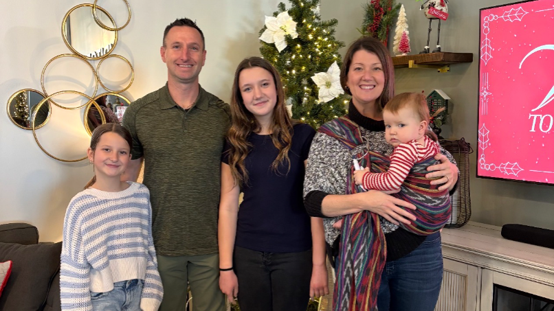
Standing with Holly in Her Breast Cancer Journey
First and foremost, we are asking for your prayers.As Holly begins her journey through a breast cancer diagnosis, our greatest hope is not found in a...
Loading...

Help Support Independent Media
SUPPORT INDEPENDENT MEDIA! If you appreciate our independent media effort, please support us to fight censorship! We are being silenced in every front...
Loading...

Support Family Along during Recovery from Surgery
Hello my name is Allison and I have been out of work since November due to a new diagnosis of epilepsy. I will be undergoing brain surgery the first w...
Loading...

Rebuilding After Stroke, Loss & Hardship
Help Me Through This Difficult SeasonMany of you know me through my writing, music, fiber arts, or our fellowship in Christ. Asking for help is not so...
Loading...
Help my mom
Update: Unfortunately my dad passed yesterday morning. My mom could really use all the support while we navigate this new part of our lives. We...
Loading...
Reliable Help is On the Way! I do need a car!
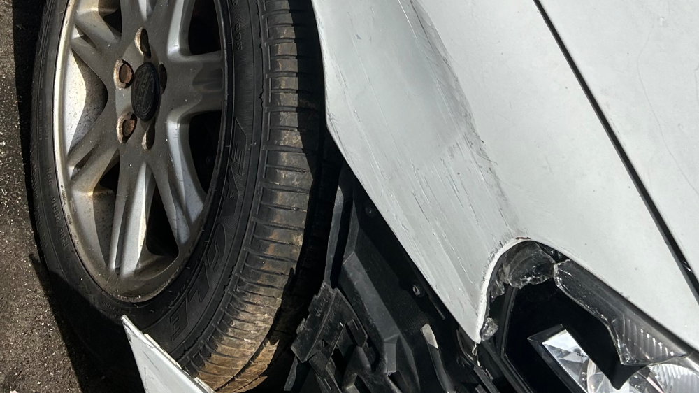
I’m asking for community support. Many of you know my son Blais died in a motorcycle accident just over a year ago on September 30, 2023 I went into a...
Loading...
GiveSendGo
The place where help and hope go hand-in-hand.
